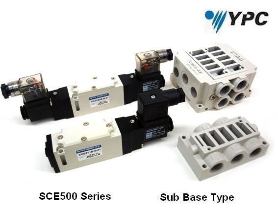
Pneumatic directional valves are used to start, stop or simply change the direction of the air flow as per the requirements in compressed air systems. Compressed air is used by many companies for operating their equipment and tools that are used in their production process.
To actually understand how directional control valves are used, it is very important to know the different types of directional valves available in the market.
Directional control valves are designed for a variety of applications, companies might use a single type of valve for any specific task, or they might use a combination of multiple types of directional control valves to carry out a particular task.
All these designs are divided into designs, like a spool, sliding seal, poppet, diaphragm and rotary. Out of all these designs, the poppet and the spool are the most common ones.
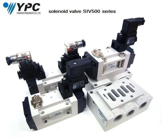
Spool Directional Control Valve
Spool valve is of two types, lapped and bonded.
Lapped spool directional control valve is designed to provide users with the flow pattern that they desire in most of the applications. The low amount of external force is required for shifting balance and this quality of the spool makes it very easy to actuate the pool.
Also during a shifting stroke the spool is designed to remain constant. This makes it easy for the spool valve to complete the stroke easily when the stiction is removed.
Bonded spool directional control valves incorporate an elastometer seal that pushes against the pressure to ensure sealing. They are designed to be used in three, position-based applications and allows you to block the blowby that comes from the exhaust when the flow pattern is changed.
They are dirt tolerant and when regularly lubricated, can last for many years to come.
Both types of spool valves are available in 3 and 4-way configurations. A 3-way spool valve can also be used as a 2-way spool by simply blocking one port.
Poppet Directional Control Valves
As the name implies, poppet valves incorporate the use of big poppet seals and its working is almost similar to that of a normal water tap in your home. The poppet seal of the valve moves in a direction that is perpendicular to the flat are of the valve and forces the annular ridge of the valve to ensure complete sealing.
Poppet valves are fast and easy to use. Their rugged construction makes them ideal for any demanding application. Poppet valves are designed in 2, 3, and 4-way configurations.
Now let us try to understand different types of valve configurations.
Two Way Valve Configuration
They have two ports that are in connection to start or stop the flow of air. They normally incorporate a solenoid shift that is operated electrically to control the flow. They are very important in any air system as it offers a very simple start-stop function, and can be used to interconnect, isolate as well as interlock different parts of the system.
For two way valve take a look here.
Three Way Valve Configuration
Three way valves are almost similar to two way valve, but they have an additional port that can be used to exhaust the downward stream of air.
They are available in open and closed configurations. They can be used for use in single or spring return cylinders. They are also ideal or use in systems where the load has to be kept in pressure with alternate exhaustion. They can be air operated as well as pilots.
They can also be used in pairs to control air cylinders (double acting) to completely replace four way valve. It is ideally recommended when there is a greater need for high speed of the cylinder.
It is because of the close coupling that the three way valves offer. Close arrangement of the couplings allows it to minimize the back pressure and drop pressure of the cylinder, allowing it to gain higher speeds.
Four Way Valve Configuration
The use the function similar to that of the three way valve, where one remains open and another one closed. They have a couple of exhaust ports that work alternately to exhaust and to pressurize.
They are ideally used in air cylinders (double acting), air motors (bi-directional), and also in different air circuits. Moreover, two air cylinders (single acting), can be operated with the help of a single four way valve.
Among the three valve configurations, the three way valve can be very confusing to install. Functions like the jog-type applications of the cylinder and emergency stop are unnecessarily asked to perform, without even actually understanding the complexities and the rise of the cost it can result in.
To avoid this confusion and eliminate the rather expensive complexities, it is better to examine the below mentioned factors-
- Is cylinders, emergency stop actually required in retract or extend phase?
- Stopping the cylinder in its mid-stroke is actually required?
- Is jobbing, during retract or extend phase absolutely compulsory?
If the answer to all of these questions is yes, then only go ahead with performing the function. Apart from making things difficult, it can many times also result in a variety of safety hazards.
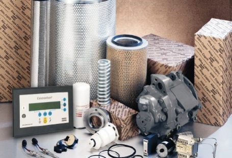
Maintenance
Scheduled maintenance is the key to ensure that your directional control valves operate at their best. Let us have a look at some of the things you can do to ensure their flawless performance.
You should schedule the maintenance and lubrication to ensure that the valve is at its optimal condition. The person responsible for maintenance should have adequate knowledge and should keep records of the dates and tasks performed on the valve.
You can maintain a checklist that needs to be filled to ensure all the basic aspects of the valve are properly covered.
It is also useful to maintain the records of the parts replaced, date of servicing, serial number of the valves, and date of lubricating oil change for quick reference in future.
Review all the records once in a year. This will allow you to get an idea about the malfunctioning that takes place regularly. You can take the required action to eliminate this problem to ensure that the chances of breakdown and maintenance costs are reduced.
PS. Since its 28th December as time of writing this I wish everybody happy new year 2017.

2 comments On Directional Control Valves Explained
ATT: SALES
Kindly quote us for the following;
-Emergency Directional Control Valve
Type: UP/122152/45
Pilot: 3.3 + (0.2 * OP) -17
ISO – CODE 199
Quantity: 06
Awaits your quick reply.
Regards,
Jacqueline
What’s up,I read your blogs named “Directional Control Valves Explained | E-Pneumatic Blog” regularly.Your writing style is witty, keep it up! And you can look our website about proxy.